 |
 |
 |
 |
 |
 |
|
Gladstone, an LBSCR class B1 (designed, William Stroudley C. 1882)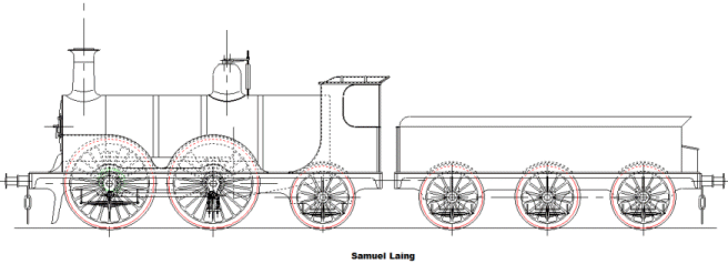 The LBSCR locomotive Gladstone was designed in response to ever greater demand for fast heavy services between the capital and the coast. Perhaps it is not what we might today consider to be an express pasenger locomotive but by comparison with the early Stephensons 0-2-2 locomotives, Gladstone with it's 18 ¼" x 26" cylinders and 6' 6" driving wheels, it was a large engine. 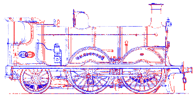
The lineage of the Gladstone is quite clear in the other prior locomotives that Stroudley designed. In simple terms the Gladstone class was based on the Richmond class that preceded it. The image, left, overlays the two classes of locomotive with the larger Gladstone in blue, and the smaller Richmond in Red. From the overlay image, it's clear that the Gladstone boiler was larger, and the cab moved rearwards to allow for this. It's also apparent that although the main dimensions of the axle centres are the same, there are minor differences at either end to allow for modifications to the guard irons and the repositioned cab. What's possibly not so clear is that the boiler barrel is actually slightly larger in diameter, there being a step between the barrel and the smokebox on the Richmond, and a through line on Gladstone. The larger boiler gives away the other unseen difference which is that the Gladstone class has larger cylinders than the Richmond. These it would seem are inherited from the C1 Jumbo class, the development of which divided the Richmond and the Gladstone classes in time. In turn the Richmond class was a close relative of the Lyons class, mixed traffic locomotive, which preceeded it. The Lyons class was essentially a Richmond, with smaller wheels, and another attractive locomotive. The Lyons class was a close tender based relative of the D class tank engine. Overall the lineage of these locomotives shows how Stroudley developed his fleet gradually and in line with demand. Sometimes the locomotives he developed were "under boilered" and I think this reflects the difficulty in predicting such complex parameters, given the pioneering approach of the time. Overall, each of his locomotives was a distinct improvement on that which preceeded it. The drawing at the top of the page depicts my bare-bones rendering of the Gladstone class, and shows the state of development of my drawing, in the form of a general arrangement. What you see is currently what I have drawn. Although it might look complete, it is far from that. Some of the areas that still remain for consideration are as follows;
In simple terms this means all the technically difficult bits. The drawings are already being scaled for 5" gauge. This will mean that some compromises will have to be made, particularly in respect of the complex details. Irrespective it is more difficult to find out how the original locomotive is configured in the details. The information gleaned this far has mainly been that available from books, but I'm now reaching the stage where the availability of required information is limited. The actual locomotive will have to be visited to find out how some things were done. Whilst it would be a simple matter to go forward designing parts anew, that is not the objective of the excercise. Although compromise will be necassary to make a scale model, it is desirable to keep the principle of operation in the details the same where possible. The following section outlines some of the areas of particular mystery, to me at least. I have a couple more books on order that I'm hoping are going to shed some light on the subject, but I have a feeling that a trip to the National Railway Museum is in order. If you are reading this and you have knowledge that you can contribute, don't hesitate to contact me or even post to the forum at the top of the page. Feewater preheatersI think I've deduced from the pictures and text that I've been reading that the feedwater preheating system operates on the basis of exhaust steam from the Westinghouse air pump, and the locomotive as a whole. There must be some sort of scoop in the exhaust ejector system, above the blast pipe that collects a proportion of the exhaust steam. As I understand it this steam is fed back through the locomotive, into the tender where it must exit and warm the feed water. 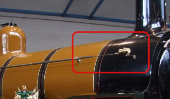
Looking at the pictures, it seems there is a control rod running through the handrail from the cab to the smokebox. Looking at the pictures it would seem that the control rod exits the handrail just short of the smokebox, and then enters a centrally sited "device" which I think controls these exhaust steam scoops. I don't know that they will let me into the smokebox at the NRM, but I figure that the scheme is very similar to that used on Stroudley's Terrier tanks, and I'm fairly sure I can see that locally at the Bluebell railway. 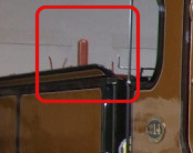
The feedwater mystery doesn't end there though! On the tender there is a tall protrusion, like a soil pipe with a domed cap on it. In British railway terms, this is an unusual looking device. I'm pretty sure that it's connected to the feedwater preheaters, and I suspect that it's a contraption similar to that used in steam ships, and other heavy steam plant. Typically the water feedpump operates on a bypass, and pumps water all the time. Closing the bypass causes the water to be forced into the boiler by the pressure of the pump. I suspect that when the bypass is open the feedwater returns to the tender via the top this protruding upstand, and that the exhaust steam is fed in around the sides. By this means the feedwater is constantly being churned through the hot exhaust steam, making it warm and preventing some heat loss in the exhaust. Another mystery is that of the actual clacks used to allow water into the boiler, but not let the steam out. Typically these are placed on the sides of the boiler barrel, or in the dome. From an efficiency perspective these are best placed towards the front of the boiler, as far as possible from the hot firebox. Cool feedwater in the vicinity of the firebox will kill the propensity to steam, but more significantly it can create thermal shock on the ferociously hot walls of the inner firebox. I seem to remember reading somewhere that one of the best approaches to feeding water into the boiler is to have entry to the boiler, for the feedwater, through the smokebox tubeplate with a baffle inside the boiler. Certainly on the Gladstones, the clacks are not visible anywhere and one can only assume that they must either be in the backhead or in the smokebox tubeplate. The final feedwater mystery is that of the pump. For sure, the Terriers used crosshead pumps, some used a duplex pump operating from the Westinghouse air pump power cylinder. Another possibility for Gladstone is that there is a tender axle pump in place. Certainly if my previous guess about the purpose of the preheat mixer tube, protruding from the top of the tender is correct, then tender axle pumps make huge sense, but just at the moment it's not clear. Overall the details of the feedwater preheating system are probably not too critical, since on such a small model the whole scheme is easily made to look real, difficult to actually make work, and probably not worthwhile. However, clacks are going to have to go somewhere, and these would probably be best situated as full size. Valve Gear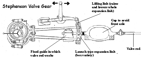
A more significant issue is that of valve gear. It is known that the actual valves are simple slide valves, and it is also known that the valves are below the cylinders. It is also known that the axis of the piston rod, and the axis of the valve spindle are spaced either side of the front axle. This is unquestionably useful knowledge, and something that will amost certainly be follwed faithfully in the model. The actual valve gear is somewhat opaque. In my mind, the valve gear either follows the tyical Stephenson pattern, or the Joy pattern. Joy pattern gear was used often on the Southern region, but it was only patented three years before the Gladstone design was completed. The Terrier tanks used Stephenson valve gear, and certainly there is the hint from pictures and drawings that I have seen that all the Stroudley locomotives up to Gladstone used Stephensons gear. Unfortunately the Gladstones have such large wheels that these hints just aren't available. Certainly the known provision of an assisted screw reverser is no clue. The screw reverser would normally be an indication of a "good" valve gear like Joy that has even valve event distribution, constant lead, and notches up well. Stephensons gear, is often not that way. 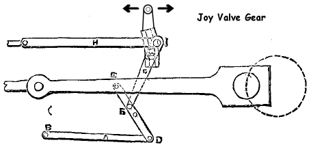
It is suggested that the air assisted screw reverser is only single acting, i.e. operates in one direction. Supposedly the weight of the motion means that the assistance only needs to operate in one direction. Typically Joy gear should be fairly well balanced at the reverser, simply because of it's inherent geometry. By contrast, Stephensons gear is heavy at the reverser, at least without a balance weight, because the reverser must lift the linkage. Another issue is that the pattern of Joy valve gear is most normally associated with valves that are above the cylinders. There is nothing to say that the Joy valve gear pattern could not be applied to slide valves below the cylinders, as in the case of Gladstone. This would though, have been unusual for such an early implementation, given Stroudley's inherent step-by-step conservative appraoch. The final issue to confuse the picture still further, is that it is clearly stated that Stroudley was concerned about the size of the crank webs, particularly in relation to their strength. One of the most significant benefits that Joy valve gear offers is that it requires no eccentrics, unlike Stephensons valve gear. These eccentrics would typically be on the crank axle of an inside cylinder locomotive, and would cause the crank webs to be thinner, to make room for them. Knowing what I know now, I would suggest that Joy valve gear would be the most sensible choice for the locomotive. Unfortunately it is not clear if Stroudley knew then, or if he would have chosen that way if he did know. Even if the real Gladstone used Stephensons valve gear, Joy gear may still be a better choice for the model simply on the basis that it would work better. Deviations from full sizeEven at this early stage, there are two variations to the full size locomotive that I am certain of. Firstly, the regulator will be of the screw type. The full size Stroudley regulator, I am certain works well. For a model, especially one with such large wheels, the screw type regulator affords a level of control not necassarily available with the stroudley type regulator. In full size Gladstone never had superheaters. To work well, a model really needs the "hit" it gets from a radiant superheater, not only that but it helps to keep the exhaust steam dry. In full size the exhaust stream goes way over the drivers head, but with a model, it tends to aim for the middle his face. There will undoubtedly be other differences from full size, watch this space to find out what they are! |


Copyright © Solid Fluid 2007-2025 |
Last modified: SolFlu Fri, 21 Aug 2009 23:34:40 GMT |