 |
 |
 |
 |
 |
 |
|
The inverting amplifier configuration
The diagram illustrates the inverting amplifier configuration for an Op-Amp. The operation is pretty straightforward once you get down to it. I mentioned briefly before about Laplace and Calculus, this will give a more accurate representation of the relationship between the input and output signals with respect to time. Considered one stage at a time, with respect to a step input it's actually not as complicated as it may sound to understand the effect of a simple delay in the loop. Certainly it leads to some interesting results and conclusions, but as an initial encounter it is way more than necessary to make accurate predictions about basic behaviour. In my mind, there are three ways to derive the behaviour of the inverting amplifier configuration. The first is a simplified version, which lends it's-self to the descriptive generation of the basic equations. It doesn't describe the Op-Amp mathematically. In this derivation the behaviour of the actual Op-Amp is built into the initial functions by reason. To my mind that's easier to understand. The second way is purely mathematical, and I don't try to describe it in any detail. Once you understand how the inverting configuration works, you'll see how the second derivation works. The third way, I don't describe here, but that's the method using Laplace. We'll consider a step input from initial conditions where both the input and output is at a zero potential. Nominally the step voltage is of unit size, and the description assumes zero delay through the Op-Amp and wires. The step in voltage occurs instantaneously. 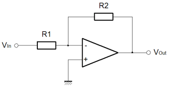
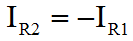
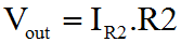
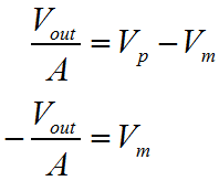
The non-inverting input is directly connected to ground. The combination of R1 & R2, act to maintain the difference in voltage between the Op-Amp inputs as small as the amplifier gain will allow. Although the inverting input will not always be zero volts during transients, it can be assumed that it is in the general case.
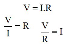
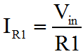
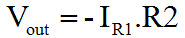
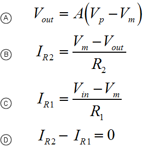
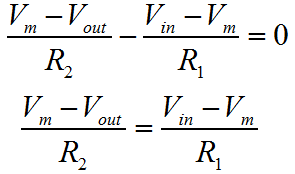
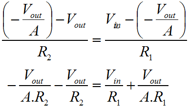
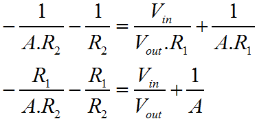
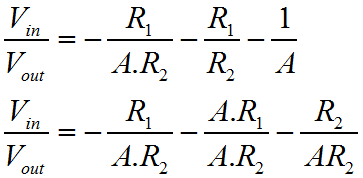
That's pretty much it. If you're in a hurry, and can't remember which way around things work, this is the ideal way to refresh your mind. You don't need a book, you can work it out on a piece of paper in 30 seconds, with nothing more than a pencil. The problem with the previous derivation is that it doesn't make any account of the actual amplifier gain. As I described the first three functions, I was making many assumptions. I hope that these are as natural and obvious to you, as they seem to me. Equally it's really quite important to state that the previous derivation isn't really "correct"; clearly it comes up with the answer you want, but it makes no account for the Op-Amp gain. 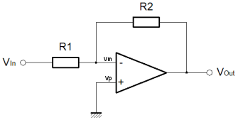 The variation of the derivation below is the strictly acceptable version, as I worked out here. It takes a bit longer, and you have to bash the rust out of your algebra! Rather than start with a rather "fast and loose" approach to generating the first equations, we'll use the basic form for the ideal behaviour of an Op-Amp. We'll then use Kirchoff's Current Law to define the circuit behaviour. Ultimately we'll arrive at the proper definition of the inverting amplifier, which includes both the programmed gain from the resistors, and the gain of the actual amplifier.
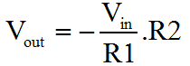
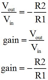
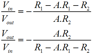
As you can see when A (the Op-Amp gain) is large, as it normally would be, then it dominates the function and causes the ratio of the two resistors to be the most significant influence on circuit performance. This is the region where the resistors control the circuit gain, or program gain, to a greater extent than the Op-Amp. When A becomes small, then the resistor ratio is much less important than the sum of the resistors. This more developed approach to characterisation of the Op-Amp is really important because an Op-Amp will rarely have infinite frequency bandwidth. We can also now see why the Op-Amp attempts to achieve a very large value for gain. The more gain the Op-Amp has the more there is available for the designer to use. Unfortunately in AC circuits, as the frequency rises the gain rolls off. This is mainly due to the parasitic effects of the transistors and other components inside the Op-Amp. Nevertheless, using our derived function one can work out how far the amplifier gain has rolled off from the program gain, by practical circuit measurements. For a given program and amplifier gain, we can then work out what the output should be at any given frequency. In an overall sense, hopefully you can see that if the input signal has a positive voltage, then the output will have a negative voltage, and vice versa. Also as the value of the resistor R2 gets bigger, the output will be bigger in relation to the input. When I use the word bigger here, I really mean the magnitude will be bigger. Obviously because the amplifier inverts, a larger gain with a positive input, will result in a more negative output. Equally as R1 increases, the output magnitude will become smaller. That's it. There's way more to this, but if you can get your head around what's written here, I think you're 90% there. On the next page we'll look more briefly at the non-inverting configuration for the Op-Amp. |
||||||||||||||||||||||||||||||


Copyright © Solid Fluid 2007-2025 |
Last modified: SolFlu Tue, 06 Dec 2011 01:39:30 GMT |