 |
 |
 |
 |
 |
 |
|
The non-inverting amplifier configuration
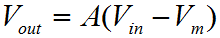
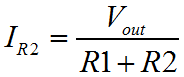
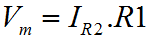
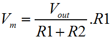
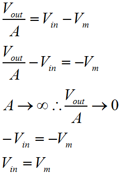
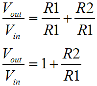
We saw the inverting amplifier configuration on the previous page. Here we are looking at the non inverting configuration, which has the characteristic that the input signal is not inverted on the output. Surprise! Besides the obvious, the non inverting configuration has some fringe benefits. Probably the most significant is that the input resistance of this configuration is as high as possible; it is that of the Op-Amp input. This configuration has no need to connect the feedback path to the input, so the input signal is not connected to a virtual ground point. No current flows in to the circuit from the input. The down side to this deal is that unlike the inverting configuration, the non inverting configuration has no capacity to attenuate the input signal. This is irrespective of the resistor values. Usually this is not a problem, but in some design situations it can be. Certainly, if there is an ambiguity as to the gain that will be required in the final circuit, the non-inverting configuration is probably one to avoid. If you're not sure if you'll need to amplify or attenuate the signal, a change to an attenuating configuration will require ripping up the physical circuit and not just resistor changes. 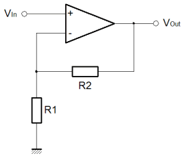 Last time for the Inverting amplifier I produced two separate derivations for the behaviour of the circuit. One was a shorthand way, another was a more formal way. I wanted to save some time this time, and so I've gone for a single halfway house. This time I've derived the behaviour of the circuit, without the gain of the amplifier included in the final equation, even though we start out defining the circuit in terms of the basic Op-Amp behaviour. The circuit input is connected directly to the Op-Amp non inverting input. We can expect that the other, inverting input, will be caused to match the potential on the non inverting input. This occurs since a rising voltage at the non inverting input causes a rising voltage on the output. Some proportion of the output voltage is fed back to the inverting input of the amplifier, by means of the resistive divider R1 and R2. Because of this feedback, the output will reach a voltage broadly in proportion to the resistors R1 and R2, where the difference between the Op-Amp inputs is more or less zero.
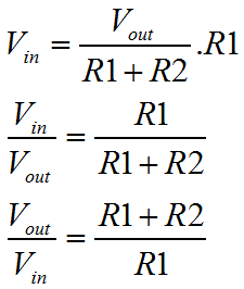
Now we can see how this configuration can never attenuate. The ratio of the resistors controls the gain, just like it did with the inverting configuration, but this time, we have the "1" term. Even if the ratio of the resistors is tiny, or even zero, the amplifier gain can never be less than 1. Physical resistors never have negative values. (That is not the same as negative resistances, which can exist.) So, that's the non inverting configuration. We've pretty much completed the square here. When you think about it, the non inverting configuration with a zero resistor ratio would be the same as the unity gain buffer I described on the page that describes the basic Op-Amp. With R1 nearly infinite, and R2 zero, the gain is simply one. If you understand the inverting and non inverting configurations, in terms of both voltage and current, you will certainly get to the stage when you can look at almost any Op-Amp circuit and simply visualise the function that it implements. This is not completely true in respect of active filters, which are AC frequency selective circuits. With such circuits, the only real way to visualise the response of those circuits is to build them, calculate them mathematically or simulate them. Even so, for the simpler circuits, it will be possible to make broad assumptions like "it's a high pass filter", "it's a low pass filter" and so on. Certainly as filter circuits become more complex, it is very hard to make broad assumptions. Since we're talking about frequency again, and we'll say much more about it later, it's worth thinking again about the effects of bandwidth on the performance of the Op-Amp, and the circuit as a whole. Just like with the inverting configuration the circuit performance will be affected by the Op-Amp gain. I've only partially done the derivation. Perhaps something to try is to finish this derivation, and find the gain equation including the 'A' amplifier gain term. |
||||||||||||||||||||


Copyright © Solid Fluid 2007-2025 |
Last modified: SolFlu Tue, 06 Dec 2011 01:50:18 GMT |