 |
 |
 |
 |
 |
 |
|
Three terminal adjustable linear regulator calculation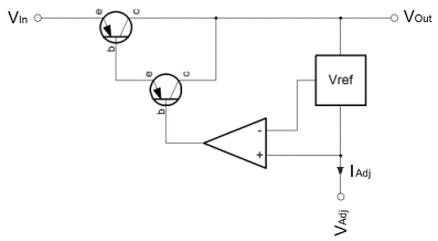
Over on the right is a diagrammatic representation of the age old adjustable three terminal regulator originally designed by Bob Widlar, way back in the 70's. These three terminal regulators are more or less everywhere. I don't know, but I'd speculate that perhaps there is one of these on the Voyager 1 probe, currently the furthest man made object from good ol' earth. You know, I'd be happy to be corrected on that, but if it's not in the probe then there will have been one in the test kit that was used to validate the probe before launch. These things are everywhere. Really, I've put this page up, because there are a few things that I always forget, and often they're not on the datasheet. Recently NXP have been offering a modern, but compatible version (NX1117) of the original LM117. On the datasheet these devices will always show an internal voltage reference which sources power from the input of the regulator. The NX1117 is no different in this respect. I'm sure that showing the regulator with the reference connected to the input is a more "correct" representation of what is actually happening internally. Alas, if like me you force yourself to derive the transfer function of the part in the hope of making your maths rust free, you'll be scuppered if you take the datasheet diagram at face value. 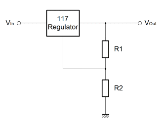
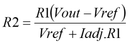
The thing here is that the internal voltage reference "appears" to be connected to the output of the regulator. Importantly, the reference voltage imparts a potential onto the output resistor (R1) which in normal conditions is 1.25V. That's it. So, when you try to use the datasheet diagram (with the Vref block connected to Vin), and you try to numerically describe, various combinations of voltage reference connected to the input; just remember that the real datasheet drawing is misleading. The drawing above shows the reference connected in a non-standard way. If you do try to understand the internal operation of the common three terminal adjustable regulator it will be useful to see it this way. So that you can see how I arrived at these conclusions you can see my working, the derivation, here. Well, these little regulators are great, obviously you'll need to look at the datasheet for information about providing bulk capacitance to ensure stability, but other than that they are easy to characterise, work well and have a long life. In fact, the only minor fly in the ointment is the adjust current. For most purposes it is a good option if circuit characteristics can be mathematically resolved to component values. Practically, one would ideally aim to use standard fixed resistor values, rather than resort to the use of potentiometers. Clearly these require tuning, and in some cases can un-adjust themselves in shock and vibration situations. 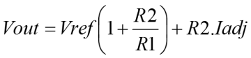 Unfortunately the adjust current interferes with the ideal where a ratiometric relationship between resistor values can be established and used to select component values. In consequence, this can lead to a certain amount of trial and error when it comes to selecting resistor values for a given output voltage. As it happens the adjust current actually informs a practical solution that works fairly well. The adjust current is a fairly small current that is emitted from the adjustment voltage pin of the regulator. Nominally it is about 52uA at room temperature, but it varies quite strongly with temperature. Perhaps as much as ±10uA over a 150°C range. Because of this variation, it is quite important to ensure that the current flowing in the programming divider is much greater than the parasitic adjustment current. In the linked derivation you will see a note that shows a recommended maximum value for R1 of 480ohms. This keeps the programming current fairly large relative to the parasitic adjustment current. If one chooses a standard value of resistor somewhere between one and 500 ohms, it should then be possible to calculate a precise value for R2 by rearranging the derived characteristic above. The only problem is that it is unlikely that the value of R2 will be coincident with a standard resistor value. The solution is simply to build R2 from two standard value resistors arranged in parallel. In the end, it's just as easy to select parallel standard resistors to achieve a precise arbitary value, as it is to choose a pair of standard resistors that achieve a precise ratio. As it happens I have prepared tables for both scenarios here.
Vref = 1.25V & Iadj ≈ 52uA @21°C
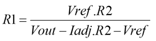
It is possible that one might wish to calculate R1 from a given R2, not what was envisaged in the procedural outline above. For this reason both equations have been developed. |


Copyright © Solid Fluid 2007-2025 |
Last modified: SolFlu Thu, 28 Mar 2013 01:24:47 GMT |