|
Working |
| |
Some of the examples in this section include mathematical formulae. Where the full derivation is not included, my working is shown here. |
|
Resistor Combinations |
| |
Lookup tables for establishing the value of resistors in pairs. These are provided for the E24 series over as many as three decades. Parallel, series, product and quotient targets are computed. |
 |
Linear Regulator |
| |
Derivation of regulator characteristic, and equations for resistor value calculation. |
 |
Parallel Divider |
| |
Derivation and calculation of resistor values for a parallel divider / termination network. |
|
Parallel Divider Impedance Calculation
So, this one might seem a bit random. It justifies it's existence because it's the kind of thing one might find one's self thiking about when in a hurry. It's a simple little thing, but actually it requires a little bit of thought to get from the idea to the reality. If you're in a hurry then the thought might not immediately come. This page is here to hold the salient facts for that inevitability.
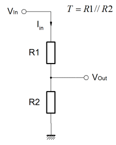
When developing some analogue or mixed signal control or signal conditioning circuit, it's often useful to get a specific voltage with a controlled source impedance with a division ratio. Obviously one would need a voltage source to drive the divider, but a single voltage source could drive more than one controlled impedance output. Equally, the divider can be used as a terminating impedance. This is especially useful in medium to high speed logic systems where series termination is inadequate, or perhaps level shifters and logic family compatibility interfaces.
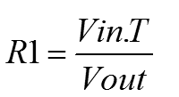
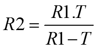
The circuit is nothing more than a simple voltage divider, but the equations provided here allow one to calculate the division ratio at the same time as specifying the parallel equivalent resistance of the resistor pair. Clearly, it assumes a low source impedance from Vin and Gnd. For such a simple problem, the maths is surprisingly involved, the working can be found here.
The only important thing is that "T" is considered to be the "effective" impedance of the path from Vout to Gnd. Essentially this is the same as the parallel resistance combination of R1 & R2. That's it!
|