 |
 |
 |
 |
 |
 |
 |
|
MSF Rationale
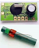
It's probably reasonable to ask, at this stage, where I'm going with all of this MSF stuff. In the simplest possible terms I just thought it might be a good idea to brush the cobwebs off my analogue electronic design skills. I recently met with a potential client, and I think he felt that my electronics background and capability were somewhat suspect. I missed out on a potential job. I'd already been thinking about the possibility of working with mechanical clocks. In connection with my interest in steam engines, old fashioned horology too is an interest. I'd been thinking about the possibility of making a master clock for setting and calibrating mechanical clocks and watches. To accomplish the task of setting a mechanical clock accurately one requires a frequency standard. Also it is clearly important to determine the current time. Less so, perhaps, the date. Nominally, a frequency standard is required for setting the speed of the clock. Usually this is done by interfering the mechanical clock ticks with a frequency standard. In this way an error can be calculated in a very short time, and corrected for. This can be preferable to the traditional way of setting the clock speed. Typically this involves the observation of drift over days, weeks and possibly months. Only after this elapesd period can the drift be calculated with reference to a master clock. The MSF signal is quite ideal for this purpose, as has been seen. Not only does it indicate, with some considerable accuracy, the date and time; it also contains a built in frequency standard, the carrier signal. The only obstacle between me and setting a mechanical clock, is a method of receiving MSF. There are a number of systems available off the shelf from varous sources. Most are of the basic radio controlled wall clock variety. These are superb for telling the time, clearly a critical requirement, but not so helpful for generating a frequency standard. The problem does not really change, even when drilling down a level. One can buy a basic receiver/antenna "matched pair", in the form of a single chip hybrid / module. The Galleon Systems EM2S is a good example, but unfortunately it does not have a frequency standard output. The 60kHz reference signal is present in the module, but unavailable for use. Having done some research, I have found there are quite a few examples of people bulding radio clocks on the internet. All but three seem to have used this EM2S module or another very similar product. In general these quite admirable projects have all implemented PIC / AVR Microcontroller implementations of the clock. In general, these have focussed on the display and decoder aspect. Some have used nixie tubes, some LCD displays, some seven segment. Few have attempted the actual radio design. There seems to be three obvious projects that have bucked this trend;
For me, I felt that all of these approaches, had merit, but I was adament that I wanted to do the radio design, and to make it from the most basic components possible. Most significantly the design had to be reliable. Alone, these requirements would suggest the use of the EM2S module. As a commercial project that undoubtedly is the right route to follow. Mainly it's less interesting to me, and I mustn't forget that there's a point to prove about capability! Overall, I had some reservations about the superhet design approach. The MSF radio system is a very precise single frequency system. Although a superhet receiver is a more interesting design, it's main practical benefit is that it can maintain sensitivity and selectivity over a wide range of different frequencies. Although globally there are a number of different systems for the distribution of clock and frequency information, I think it would be rare for a single receiver to need a dynamic tuning capability. It magnifies the complexity, and increases the cost. Although the frequency standard radio, is a good design, it doesn't have an AGC capability. For it's designer, I'm sure, this is just to keep things quick and simple. I really wanted a radio that I could know would work anywhere in the UK, where a signal is receivable. The frequency comparison hardware and software is very interesting because that's one of the uses I have for the final instrument. I think to start with I just need a working receiver. The EM2S module is interesting, because it's almost certainly a TRF. TRF receivers are an old approach to radio. In the early days, it was the most obvious route. The development of radio meant that people wanted to tune their receivers to different stations at different times. A TRF uses cascaded stages of amplifiers coupled with LC filters. The big problem with them, is that when one tunes a receiver one will only want a single tuning knob. Keeping the cascaded LC filters tracking the tuning knob properly is an almost impossible problem to resolve. The selectivity of the receiver is always poor when used to receive a variety of different frequencies. The EM2S module uses some kind of regenerative crystal filter. The crystal is so selective, that that the radio only needs a single stage filter. I figured that the core of the issue is somewhat masked by this crystal filter. The EM2S module is implemented as a monolithic semiconductor device. This makes it difficult to use inductors on chip, and using them off chip is almost as inconvenient for mass production. In principle, there's no practical reason why a similar design in descretes could not use LC tuning stages. Although each stage must be tuned, it only need be done once, there are no tracking issues. Finally, I really liked the "op-amp only" approach. Op-amps are cheap and easy to use, the radio frequency is quite low for MSF, and there is no frequency constraint preventing almost any general purpose op-amp being used. The real problem comes from the signal size. Although the signal size is not yet known, I fully expect it to be in the order of hundreds of nanovolts. This kind of signal is so small that it dissapears into the offsets, and input protection of an op-amp. Chopper op-amps can be used for signals like this, but they're not so good as the frequency rises. An Op-Amp could be used in an open loop configuration, but the disadvantage is little control over the gain. Certainly AGC is outside the bounds. These then are the initial considerations when approaching the receiver design. In the next pages, I'll set out some further research, define some requirements in detail, and begin to simulate the design. Once I'm happy that the design can work, we'll commit to parts in a schematic editor, walk through footprint creation and the PCB layout. We'll make a high quality board at home using basic materials. Then we'll think about test equipment, and setup, debugging and verification. When we get to the end we'll have a working MSF radio. |
Copyright © Solid Fluid 2007-2025 |
Last modified: SolFlu Fri, 19 Apr 2013 22:42:36 GMT |

