 |
 |
 |
 |
 |
 |
|
The comparator and hysteresis
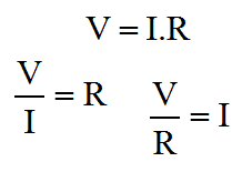
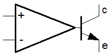
Now we've seen the basic linear configurations for the op-amp, it's probably time to remember that the little beastie can be used as a non linear device. Initially we'll not be using any feedback whatsoever, but later we'll look at positive feedback, unlike the nice stable negative feedback which we've been thinking about so far. When we first thought about the Op-Amp we were thinking in terms of the open loop performance of the basic Op-Amp. We pretty quickly looked at "closing the loop" because we wanted to get at the fuzzy stuff. Although we can think about the Op-Amp as a pseudo logic device, it's quickly clear that the real benefit is its ability to signal voltages that are somewhere between the power supply rails, and not just at the limits of the output, like logic. With the comparator one is usually, but not always, at the end of some chain of analogue signal conditioning function, looking to feed a signal from a sensor into a binary device, perhaps a switch, perhaps logic, perhaps a microprocessor. The interesting thing here is that the analogue world from which we are getting the signal, will inherently apply some meaning to that signal. Because of that meaning we'll want to apply a threshold. Above the threshold has one meaning, below it another. Applying meaning to a signal in this way is what we do in a comparator. Another more generic name for the function is a discriminator. There is such a thing as a frequency domain discriminator or frequency discriminator. Here, the comparator is simply a time domain discriminator. Like most discriminators, the behaviour is nonlinear, like logic. Although the circuits I'll show here are basic in concept, they really shouldn't be overlooked. The primary reason for this is that these concepts lie very much between the analogue and digital worlds. They are a bit of both. This connects with the idea of hysteresis, which I already mentioned. By using analogue feedback techniques which are intentionally unstable we can enhance the digital performance of the discriminator, with hysterical behaviour. Such behaviour is also known as the Schmitt Trigger, we'll look at that when we've seen the basic comparator. The comparatorThe circuit below depicts the Op-Amp in the comparator configuration, and I've added a transistor output stage. The transistor is used here as a switch. It will become completely clear why it's needed later. For now, the easiest thing to do is to think about it as a nice way to interface with TTL. TTL is perhaps the most ubiquitous of logic families. TTL stands for Transistor Transistor Logic. As the name implies, logic devices typically use transistor on both the input and output. The logic family is very much diminished today (but not obsolete). Importantly, many of the most up to date logic systems will provide a simple way to interface with TTL signalling levels. 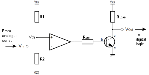 The comparator configuration uses the Op-Amp "open loop". There is no feedback at all. We saw how a tiny difference between the Op-Amp inputs caused a huge swing in the output, because of the large Op-Amp gain. In the comparator circuit, we use the divider (R1 & R2) on the non-inverting input to set the threshold voltage. The input to the circuit is connected to the inverting input, of the Op-Amp. If the input is high, the output of the Op-Amp is low, and vice versa. You can see this behaviour in the analogue truth table on the basic amplifier page, above and to the left. The Op-Amp output swings between its maximum and minimum levels, and unless the amplifier has rail to rail outputs, this will be somewhat less than the actual supply rails. This arrangement of the circuit input causes the Op-Amp to invert the signal. The transistor inverts the signal again to make the output positive logic. The resistor (Rlimit) limits the current in the base emitter junction of the transistor. Since the Op-Amp output could be as high as the supply rails, and there is only a diode drop between the supply rail and ground through the transistor, a current limiting resistor must be used. The resistor (Rload), limits the current on the collector, and is known as a load resistor. When the transistor is on, current flows in the load resistor, and a voltage is developed across it which can be seen at the output. When the transistor is off, no voltage is developed, and the output voltage sits at the supply potential. You can now see the inverting action of the transistor. In particular, when the circuit input is high, the Op-Amp output is low, the transistor is off, and the circuit output is high.
In these examples, the amplifier, and the output transistor are shown separately. This need not always be the case. The LM211 is a good example of a dedicated comparator. The LM211 is an Op-Amp, but instead of the typical push-pull or totem pole single ended outputs typical of an Op-Amp, the emitter and collector of a transistor are exposed as the outputs. This simple modification to an Op-Amp reduces component count, and allows the chip designer the ability optimise the device for switching speed.
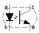
It's important to remember that most transistor output comparators are not truly isolated. On the face of it, it's easy to think that one could connect just about anything to the emitter and collector output pins. This is simply not true. When you look at using such devices you have to look carefully at the data sheet. In some cases, the output pins can only be connected in particular ways to get the right kind of functionality. Whilst there is some latitude in what you can do with these combined devices, in extreme cases you may have to resort to a fully isolated scheme using an opto-isolator. As you can see below, even the simple divider relationship is actually quite complex. You can see that the switching threshold is specified by R1 & R2. For the forward engineering task, nominally the sum of these two resistors should allow a current to flow which is perhaps 10 times greater than the leakage current into the non-inverting input. The ratio of the two resistors sets the actual switching threshold, as a proportion of the total voltage between the supply rails. 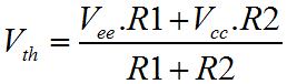 A similar "factor of ten" strategy can be used for the output transistor. Typically the load resistor would be arranged to allow sufficient current to flow in the "output high" (transistor off) such that the logic stage coupled on can achieve its input high logic level requirement. Once the load resistor has been established, the datasheet for the transistor will yield a gain (hFE) which can be use to calculate a base current. The base current can be calculated because the maximum output voltage of the Op-Amp is known. It's generally half of the "output swing". With the gain of the transistor (hFE), one can calculate the smallest base current that will drop all but the 0.7V emitter diode drop in the load resistor plus any current that might enter the circuit output from the logic stage that follows on from the comparator. So far the broad assumption has been that the logic that follows the comparator will be powered from the positive analogue supply rail, and the analogue ground. In some cases the logic may use supply rails that are derived from the negative supply and ground. In others the analogue supplies might be completely isolated from the digital supplies. In each of these cases alternative solutions are available. For the negative rail solution, the transistor and load resistor can be connected between the negative rail and ground, as shown below. 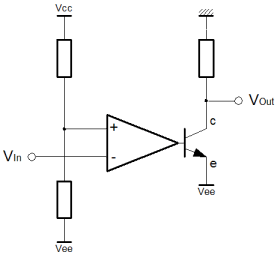 For complete isolation, an opto-isolator can be used as shown below. An opto-isolator is simply a transistor, where the base connection is replaced by an LED. The complete device is encapsulated in ceramic or plastic, and the internal light intensity is analogous to the base current in the conventional scheme. In this scheme, the analogue supplies are completely separate from the digital ones. This is known as galvanic isolation. No charge carrying particles, electrons and such, can flow between the separate circuits. 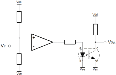 This has many benefits, particularly in high voltage, or high sensitivity applications. True isolation allows the option for the comparator circuit to float. Although it might have supply rails of perhaps 12v, the analogue ground potential could be 1000 volts. The true isolation allows an optical couple direct into 5 volt logic directly referenced to true ground potential. In the same way, high sensitivity applications demand that the supply rails are clean and free of noise. These noise signals can "leak" into tiny analogue signals. If the digital and analogue supplies have a common ground it is difficult to separate the inherent switching noise of the logic from a sensitive analogue circuit. The opto-isolated configuration of the comparator can help with both of these problems. The Schmitt TriggerDigital (logic) systems are intended to be fast. They're twitchy. For noise immunity their ideal switching thresholds would be widely spaced. Actually, this is how the acceptable range of input voltages to a logic device are specified. In practice, the actual logic will normally have a simple single threshold voltage. The manufacturers of the devices are issuing a caution. They warn that they have only implemented a single switching threshold. You as the designer connect your miscellaneous analogue circuit at your own risk. To minimise the risk, you must ensure that your signals provide adequate "noise margin". You can do this at your interfaces using the Schmitt trigger. For simplicity and switching speed, combinatorial logic has no internal feedback. For a given input, there is a given output, after a propagation time. This is analogous to the basic comparator. The problem with this single threshold chip design approach is that if the input signal hovers close to the switching threshold, then any noise on the input will cause the output to rattle. I'm avoid the word oscillate, because that is associated with feedback phase shift and resonance. Here, the rattly nature of the output is caused by the minute AC noise signal that sits on the DC signal which is hovering near the switching threshold. Notwithstanding, rattle and oscillation look very similar on an oscilloscope. When dealing with sensor signals, the signal could be anything, and it will almost certainly have some degree of noise associated. If we don't protect the logic from this hovering situation, a whole huge chain of combinatorial logic can be caused to rattle. It rattles in sympathy with a single slightly noisy analogue input signal that is hovering. Even where sequential logic is used, the difference between analogue and digital systems can still be problematic. Where an analogue input that is hovering, feeds directly into a flip-flop, it can still cause combinatorial logic inside the sequential system to rattle. Though the flip-flop would appear to protect, it cannot always, and this is known as a metastability problem.
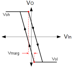
Hysteresis can fully and properly protect against these rattle problems. For a given threshold, positive feedback on an Op-Amp can be used to move the input threshold up and down in opposition to the input signal such that hovering cannot occur. When the input is large, the threshold is low, and when the input is small, the threshold is high. The threshold moves to avoid the input signal. Since we're using an Op-Amp, the parameters are controlled by resistors, and so you have control of where the threshold is, and how much it changes by. In this way one can construct a real noise margin, as opposed to the conceptual one associated with a logic device. The Schmitt Trigger is a very important function. Adjacent on the left you can see the basic graph of hysteresis. It confirms the idea, as described above. Nominally the switching threshold is at zero, but you can clearly see how the graph actually passes either side of the origin of the graph. The arrows on the graph lines show which way the characteristic passes the origin. When the output is high, the threshold voltage is considerably lower than when the output is low. This has important consequences for the hovering scenario described previously. If the input hovers around the switching threshold, and some small quantity of noise tips the balance, a momentary change of the output cannot now occur. The basic level of the input signal does not change. When the noise triggers a change in the output, the threshold voltage changes, and as long as the margin between the thresholds is larger than the noise signal, the state of the Schmitt trigger cannot change again. Using the Schmitt trigger, the rattle problem is eliminated. Below is a schematic representation if the circuit that implements hysteresis with positive feedback. As you can see the basic implementation of the comparator has been augmented with the resistor R3 which provides the required positive feedback. 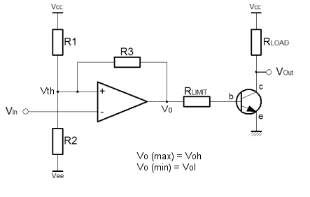 The Schmitt trigger is a more complicated circuit than the plain comparator. The arrangement shown above is not the only possible configuration for a Schmitt trigger, but the one shown here inverts and uses a separate transistor to achieve positive logic overall. The inverting configuration means that the inverting input to the op-amp is free for connection solely to the input. This ensures high input impedance, which is especially useful. The alternative configuration combines the input with the feedback on the non-inverting terminal of the amplifier. The down side to this configuration is that the input is not only subject to a low input impedance, but also to the abrupt changes in the output due to the positive feedback. On the benefit side, the alternative configuration allows specification of the virtual switching point with a separate divider on the inverting input. The margin is always as symmetrical as the output voltages of the Op-Amp. In the configuration shown above, the positive feedback occurs through R3. To understand how it works is simple. Think about the divider without the feedback, and then imagine the output pushing and pulling the threshold voltage through R3. Clearly, the size of R1 and R2 affect the symmetry, not only of the virtual threshold point but also the size of the margin in each direction. This means that if the virtual threshold is below the nominal ground potential the lower margin will also be smaller. For this reason it's important to forget about the virtual threshold, except insofar as it's the point you want to switch at, but for the noise. The virtual threshold doesn't mean anything in the functionality of the circuit. All that matters to the circuit is the size and position of the margin. It's unlikely that the negative size of the noise will be any bigger or smaller than the positive size of the noise. That's just the way signals work, since they are all comprised of sine waves. This leads to the problem that when the virtual switching point is other than ground potential, the margin is also offset. All solutions are possible with just the three resistors, but you must translate between where you want the virtual switching point to be, and the middle of the margin you define. The equations below help with the task. 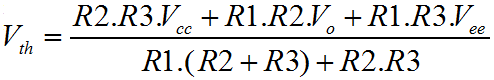 Considering the Schmitt trigger in equal terms to the comparator, to find the threshold voltage we must consider the effect of the Op-Amp output on the threshold. The equation above demonstrates a method to calculate the threshold voltage. Clearly, this is determined in terms of the resistors, the power supply voltages, and the output voltage. We already know that the output will only have two states, and so the output voltages can be fond on the data sheet for the Op-Amp in use. In the case of an Op-Amp with rail to rail outputs, these parameters will be (more or less) the same as the supply rails. 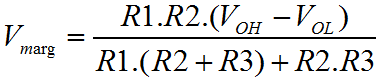 Perhaps more useful than the actual threshold points, is a way to calculate the noise margin between the thresholds. After all, the margin is the main reason to use a Schmitt trigger. Above is the equation that allows calculation of the margin voltage. 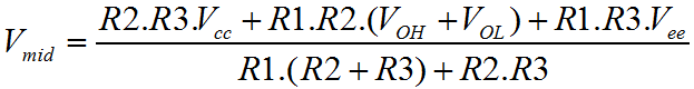 Finally, the equation above completes the picture. This equation allows calculation of the "effective" threshold voltage. This is the virtual equivalent of the original simple comparator threshold. Since the Schmitt trigger aims to adjust the actual switching threshold to achieve hysteresis, this is the threshold exactly half way between the upper and lower thresholds. With these three functions it should be possible to construct a precise functional behaviour, and make reliable connections between analogue and digital systems eliminating "rattle" and metastability in the logic, as long as the noise signal is less than the noise margin. There is a certain amount of interdependence between the various resistor values, but hopefully this series of pages has helped you to understand the function of each of the resistors. Remember the factor of ten rule described for the comparator circuit. For a fully symmetrical Schmitt trigger it is possible to set the R1 / R2 divider to specify a nominal threshold. Then rearranging the equations, the value of R3 can be calculated exactly. If there's any imbalance in the practical value of the high an low output from the Op-Amp, R1 and R2 can be adjusted to suit. As with any multi variable problem, a certain amount of trial and error will be required to get practical component values. A particular observation is that infinitely fine resistor values are impractical. Often it's faster to work with a list of available resistor values and do trial and error. Once in the ballpark you can try alternative combinations to make the inevitable compromise. A good way to do this is to set up functions like those above, in a spreadsheet. Then you can see which alternatives have been tried and which not. |


Copyright © Solid Fluid 2007-2025 |
Last modified: SolFlu Fri, 29 Mar 2013 02:21:14 GMT |