 |
 |
 |
 |
 |
 |
|
Differential signalling and the balanced line
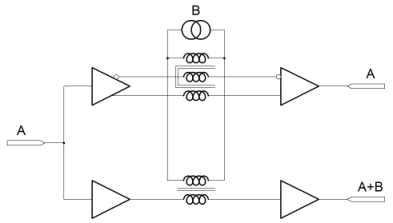
The obvious solution to the problem of communicating sensor data, is to run a wire from the sensor back to a location where more involved electronics can be placed. This has some significant drawbacks. If we run a single wire, it is inevitably referenced to a ground potential. Remembering that the sensor may well be placed in a location where even minimal electronics are impractical, it is likely that the signal from the sensor will be small and weak. A small weak voltage on a long wire from a sensor is a recipie for difficulty. Typically, radio antennas are long pieces of wire. There's nothing particularly special about antenna wire. Long wires collect radio signals, noise, and all mannner of other energy from the environment that surrounds them. In an electrically noisy environment, the weak signal from a sensor can become swamped by signals that were not known to be present at design time. The diagram on the right attempts to show a differential/balanced scheme which uses two wires to carry a signal (top), against a single ended system (bottom). The input signal 'A' is the same for both schemes. The signal 'B'is introduced to all of the three wires that carry a signal from end to end. Whereas the single ended scheme outputs a combination of 'A' and 'B' the two wire system only allows the original signal 'A' through.
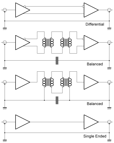
A reasonable question at this point might be, "So, how does that work then?". Actually, it's pretty straightforward. The idea is that the differential/balanced driver will place a forward potential on one wire, and a reverse potential on the other. The difference between the signals coveys the actual information. Clearly, noisy signals will still couple into the wires, but they couple into both wires equally. At the receiver this is manifest as the potential on both wires rising or falling together. Since the signal is conveyed in the difference between the potentials then the actual signal is unaffected by the noise. This kind of scheme and action is described as common mode rejection. Common mode rejection is often described in the power supply specifications for operational amplifiers. In addition, a common mode rejection figure for the amplifier inputs is usually supplied. Each describes the two wire input for signal or power, and the associated attenuation (usually in decibels) for the path from its input to the combined output. The amplifier is aiming to reject noise in any way it can, from anywhere it might come from. It is important to recognise that the power supply is as much a two wire scheme as the main signal input to the amplifier. Basic electrical theory says that a circuit must be a complete loop. If a current flows down a wire, then an equal and opposite current must flow in the ground - or the wire that represents the return path. In this light it's quite hard to draw a clear distinction between the differential/balanced scheme and a simple single ended system with its mandatory ground. On the right I've included a diagram which will hopefully clarify things a bit. Obviously the balanced scheme has no need to reference ground at all. Actually the two ends of the balanced system could be many kilovolts different in potential, and this is yet another crucial application for such a scheme. There is a specific tradeoff which can now be seen. The differential line can communicate DC signals which the balanced line cannot. Whilst the transformer isolation allows the two ends of the line to attain potentials very different from one another, the line transformer is an AC coupling scheme. Broadly this means that DC signals may not pass. The line transformers help noise immunity but they prevent low frequency signalling. The differential scheme allows DC signals to pass, but the noise immunity is less good. The shared return or ground path couples noise into the signal, and constrains the common mode range to that of the receiving circuitry. Usually long distance signalling requires the use of a transformer but badwidth is low. Local systems for, perhaps, stereo audio distribution are often differential. It is important to remember that the balanced scheme is never wrong. Importantly, with high speed digital communications or frequency multiplex techniques both DC and AC signals can be passed through an AC coupled medium. Broadly, we need something that we can drive the line from. The diagram shows how a balanced line can be driven from a single ended driver, but equally a differential line requires something more. The something more is described as a line driver, and typically it has the flexibility to be used to drive a differential or a balanced line. On the next page we'll look at a line driver in more detail. |


Copyright © Solid Fluid 2007-2025 |
Last modified: SolFlu Sat, 30 Mar 2013 16:53:46 GMT |