 |
 |
 |
 |
 |
 |
|
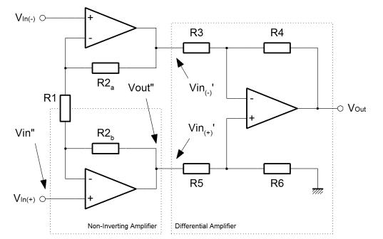
Instrumentation Amplifier
In this final page on signalling I've put up the standard circuit for receiving signal from a balanced/differential line. This circuit will convert voltage differences on the inputs, into a signal on the single ended output. It does so whilst rejecting completely signals which are common to both input lines. The circuit divides into two subcircuits that we have already looked at. The Non-inverting amplifier is straightforward, if unusually connected in this situation. Also there is a differential amplifer connected to the inside of the input buffer. Actually, two non-inverting amplifiers are connected together by their feedback paths. R1 is shared by both amplifiers. If you look back at the non-inverting configuration you'll see that the middle of R1 was connected to ground. It is likely that it would be at that potential here too. Perhaps if some noise had been coupled into the line, the potential in the middle of R1 might fluctuate slightly, but remember that the inputs are equal and opposite. The potential in the middle of R1 should always be half way between the inputs, nominally ground potential. This cross connected non-inverting configuration is quite important. Firstly it presents a very high input impedance to the line which is good for signal integrity. Mainly that feature allows the designer to impedance match the line in any way he might choose, rather than being constrained by a comparitively low input impedance of a differential amplifier. Secondly, the cross coupled configuration could be used in isolation as a line buffer or amplifier. With two inputs and two outputs, it's a great and simple way to get gain onto a long line, in either a balanced or differential configuration. Below is the equation that describes the gain of the non-inverting amplifier. Obviously in this configuration two amplifiers share R1. They actually get half of it each. You'll see that the equation tweaks this slightly, just to make it neater. Essentially it's the non-inverting amplifier equation from previously. 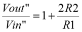 On the right of the diagram at the top is a differential amplifier. Again I've just taken the equation from the previous derivation, but the component identifiers have been changed. Initially I've assumed the differential case where the input voltages are equal and opposite. If you plug the definition into the equation previously derived, then you get the one below. We'll use this equation again later, but for the time being it is included for comparison with the common mode input case. 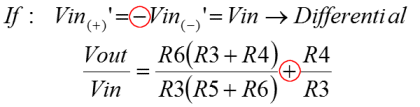 So, this time, I've made the inputs to the differential subcircuit directly equal. This is the same as a common mode input, a signal which is coupled into both lines equally. When you plug that definition into the basic differential amplifier equation, you get the result below, which differs only by the sign of the second term. 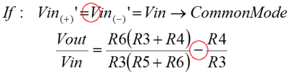 If you give the resistors of the differential amplifier a nominal value which is the same for all, and put those into the equations above, you'll see that the differential inputs are subject to a gain of two, and the common mode inputs are subject to a gain of zero! 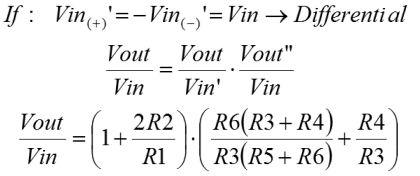 Finally, the last equation brings the whole together. The product of the non-inverting amplifier, and the differential signal input configuration of the differential amplifier, describes the gain for the whole instrumentation amplifier. I think that if one were to use such an amplifier, it is likely one would buy it off the shelf, in the form of the AD620 or one of its functional friends. Obviously, it's useful to know how an instrumentation amplifier works. More important though, it shows that the gain probably should be adjusted in the non inverting amplifier rather than the differential amplifier. Anything other than equal value resistors in the differential amplifier would damage the common mode rejection demonstrated here. Since complete, balanced, gain control can be found by adjustment of R1, it is the natural candidate for implementation as a potentiometer. |


Copyright © Solid Fluid 2007-2025 |
Last modified: SolFlu Sat, 30 Mar 2013 17:56:31 GMT |