 |
 |
 |
 |
 |
 |
|
UART - Universal Asynchronous Receiver TransmitterSo what is all this UART stuff doing then? A UART is a means of communicating digital (binary) data serially on a single wire. Technically this is known as Time Division Multiplex or (TDM). The Asynchronous part is also pretty important, in that it suggests that there is no clock signal involved, hence just one data wire. In the simplest possible terms the individual bits of a data byte are sent along the wire. The voltage on the line indicates a '1' or a '0'. For each bit, the voltage is held at the signalling level for a fixed period of time. This holding time allows the receiver to detect and record the bit, such that the whole byte can be recovered at the receiver. The graph below illustrates this point; 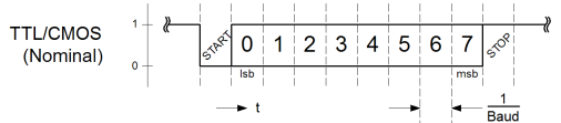
The graph shows time advancing from left to right, and the line voltage increasing vertically. No actual voltage is indicated, but instead the axis shows the values '0' and '1'. This is mainly because the diagram aims to be independent of logic technology. There are many forms of logic technology, such as TTL and CMOS each usually (but not necessarily) will have different voltage levels to indicate values of '0' and '1'. In the diagram there is some ambiguity in the actual voltage level around the bit times marked, zero thru seven. This is intentional, the diagram is intent on demonstrating the generic case. The diagram attempts to make no indication of the specific voltage level in the bit cells, because any data byte could be sent. To a certain degree the actual interface specification reflects this. The purpose of the additional start and stop bits shown, is to demarcate the boundary between individual transmitted bytes. Because the actual method of transport does not care what the sent bytes are, it must have a way to indicate the start and end of transmission. When the signalling wire is idle, it is at the high voltage level. On transmission the voltage goes low, to indicate the start of the byte, and on completion the line is guaranteed to be high for at least one bit period. When to bytes are sent consecutively, the joined stop and start bits ensure that there is always a transition from high to low before an actual data byte is transmitted. I mentioned earlier about differing voltage levels for different technologies, or logic families. From the perspective of long distance communication between different systems, this can present quite a problem. It must not be the case that different systems disagree on the voltage level of a '1' or a '0'. Since there is no rule to say how to implement a UART, and the length of the signalling wire is not known prior to connection, there could potentially be significant disagreement on the meaning of zero or one, in terms of voltage. The RS-232 standard aims to mitigate this problem. Among other things it defines the voltage levels used to represent signalled bits on the wire. The diagram that follows shows the same generic byte in transit, but this time signalling operates to the RS-232 standard; 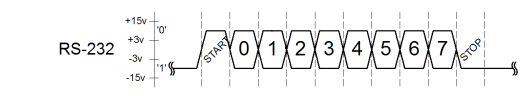
As can be seen, the data looks somewhat different. The most significant thing that has happened is that the direction of '0' and '1' has been inverted. Also, specific voltage levels have been specified. The levels shown are essentially between +/- 15v. The actual suggestion from the diagram is that the voltage can be anything up to 15v in magnitude, but that below 3v in magnitude is invalid. From the perspective of implementation, one would typically signal at 15v, but expect to receive only 3v. This caters for significant line length, in the order of kilometres. In practice links tend to be short and if greater distances need to be traversed, a modem is used. Since most hardware that typically drives RS232 does not have power supplies that meet the 15v requirement, it is common that a lesser voltage be driven. Alternative schemes are commonly used where suitable power supplies to drive only the basic +/-3v are not available. Clearly the +/-3v line requirement can only be met from a +6v (or greater) single rail supply. This is a problem for many logic families where a single supply of, at most, 5v is available. Such cases normally use a special line driver. These drivers use a "charge pump" to increase the voltage available and drive a line such that a receiver will see at least +/-3V on a moderate line length. This article does not cover the RS232 electrical interface in detail, but a typical charge pump device to drive RS232 from a single 5V supply is the MAX232. A datasheet for this line driver can be found here Another observation from the second graph above, is that the cells for the individual bits, no longer have square edges. This is because RS232 is not commonly terminated, and since a long line is a clear representation of a transmission line, edge speeds must be limited. Even though most RS-232 line drivers will limit edge speed, long lines can still see significant voltage variation from the ideal at bit boundaries. A limited edge speed translates to a slope, and it is not really safe for a receiver to accurately sample data in these regions. Having ventured into the whole issue of transmission lines, it's probably time to mention the Baud rate. From the previous para, you'll probably have picked up on the idea that the longer the transmission line is, the slopier the signal edges need to be. There's a bit more to it than this, but for this article suffice to say that it's true. If you can just accept that as a transmitter, at the far end of an unterminated line there will be a reflection back. This reflection will occur for any edges that are placed on the line. By sloping the edges they become less like the perfect edges, that reflect the best. This helps to mitigate the problem that a returning echo will add to an outgoing signal level making the signal deteriorate in quality. Clearly, the longer the line, the longer it takes for any reflections to return. If a bit is presented to the line by a transmitter, and a reflection appears in the outgoing bit, the longer the line, the more of the bit is compromised by line transients. The longer the line becomes, the longer the bits need to be present in order to allow the line to settle. Sadly, as the individual bits become longer to maintain good signalling on the line, the slower the actual bit rate becomes. There is a direct relationship between line length and speed of communication because RS232 is normally unterminated. This is still true in terminated systems, but much less so. To counter the problem (and for backward compatibility), a UART will normally allow the specification of a Baud rate by any user. This Baud value is a direct representation of the time which a bit is signalled for at the transmitter. For the purposes of good communication both the receiver and transmitter must know (and agree) what that bit rate actually is. If they don't, then the receiver will not be able to determine when to sample a specific bit of data. Although a receiver will see a start bit, without knowing the Baud rate it cannot then determine when the next bit will be present. Now we have seen what the UART actually does, we can go on to look at alternative ways to actually implement it. |


Copyright © Solid Fluid 2007-2025 |
Last modified: SolFlu Sat, 24 Oct 2009 02:37:29 GMT |