Sheet1 General Arrangement (Version 010)
Drawing Sheet
Notes
More effort was placed on the development of the couplings and the buffers at this stint. On consideration, the coupling chain is actually dependent on the size and arrangement of the buffers. The buffer heads and stocks have been redetailed and a spring calculated and added, such that the buffers can function as would be expected. With that information it was possible to recalculate the coupling chain length, and to my relief the chain now looks much more like the real thing!
Doing some research I was able to arrive at an estimated figure for the overall weight of the locomotive, with water. This knowledge, though fairly arbitary at least gives a number to work with when considering the overall springing arrangements for the suspension. My initial guess for the weight of the locomotive is about 160lb. Divided six ways I get something like 26lb per wheel. With this number I can begin to look at the leaf springs and their viability. Obviously the coil springs will also need to be calculated, but I'm confident that these can be made to work. This excercise is simply to establish if leaf springs can be made to work.
I calculate that a 4.2" by 0.25" leafspring, with five active leaves, and one attachment leaf each 0.0625" thick, in phosphor bronze (ASTM B103) would have a failure load of approximately 52lb. On the face of it, it would appear that this could be made to work. Given that we already know clearance in the splashers is tight, and that we operate quite close to the limit of the strength of the leaf springs, getting an accurate travel stop for the axleboxes seems appropriate.
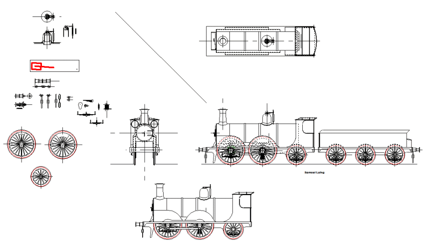
The final task was simply to make a copy of the side elevation for the purposes of printing an artwork, for the title page of this series. In the end I decided to use the drawing with the hidden detail on it. The drawing without hidden detail is shown, but in the end I felt that drawing should be coloured in to be used. It's a task I'll do, but there is still so much potential for change it seems hardly worthwhile. Perhaps I'll do it when the detail drawings are complete.
There might be a bit of a gap until the next update, because the next task really is to get myself to the NRM at York. I have a list of things I need to know before I can move on.
|