Sheet1 General Arrangement (Version 009)
Drawing Sheet
Notes
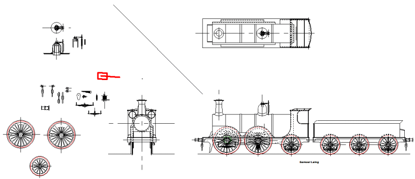
Today's effort was to put some detail into the safety valves. Since the safety valves are, mechanically, fairly independent of anything else on the locomotive, it made sense to actually work out the details prior to drawing an outline on the general arrangement. You'll notice that a couple of sectional drawings of the inner dome and the spring balance assembly appear on the left hand side of the drawing.
One of the big unknowns in the design, is exactly what the maximum rate of steam production will be from the boiler. Obviously a factor which will affect this is the heating area of the boiler, which is currently unknown. In truth it's difficult to predict the actual heat output of the fire, given varying load conditions and coal quality. Perhaps it would be easier if we were using a gas burner, and no draw from the blast pipe. The reality here is that if the steam production rate were known then it would be possible to calculate the minimum safety valve aperture from that rate on the basis of pressure and flow.
On the basis of empirical evidence I have set the actual valve dimensions such that a 1/4" diameter stainless steel ball sits on a 7/32" seat. This arrangement gives a maximum aperture fo 0.0376"2, the full 7/32" diameter, with a 0.090" lift. This is the basis for all further calculations. Two such valves are used, and at full lift this gives an effective hole diameter of 5/16", which would seem an unlikely hole to allow the raising of steam.
Given that the valve dimensions and the relative positions of the fulcrums on the spring balance are known, it is possible to choose a material and calculate the dimensions of a spring with suitable adjustment to set a valve lifting pressure in a given range. Nominally the boiler will be designed around an operating pressure of 90psi. We aim to set the parameters of the spring such that maximum opening will occur at 120psi, with a 60psi set point. Clearly the set point can be raised to 90psi by the use of the adjustment nut. The wide range of adjustment is to allow for variability in the spring, and to encourage the safety valve to sizzle, rather than to pop.
Although the actual spring is not in the path of the steam, as might normally be the case, from a materials perspective, it will be both hot (166degC @ 90psi) and potentially wet. For this reason we choose 316 stainless steel wire for the spring. With our choice of spring wire, nominal spring length and diameter and balance arm, the required spring uses 0.032" wire with 27 coils. The free length of the spring will be 1.76". The spring design has been calculated for ground but not closed ends, as is suited to home manufacture.
The spring in it's natural state is larger than the container in which it will be used. The adjustment nut may be used to preload the spring whilst the lower section is crimped or soft soldered into position. Detailed information will be elaborated when the safety valve is properly documented.
The actual dome is simply a copper/bronze disc, a copper/bronze ring, and a piece of copper tube sweated together. The valve seats are fromed directly into the top of the dome, but I think when I detail the inner dome properly, I'll change the seat. The dimensions will remain as they are, but the valve seat will be a screw in component. Any damage to the seats, does not then necessitate replacement of the whole inner dome assembly.
Whilst at it today, I thought I'd make a first attempt at the couplings and buffers. Oddly the drawhook took quite a time to make look right. I think that is mainly because the real thing had a non-geometric layout. Obviously in the CAD environment the lines all have to match up, which is not so easy when the shapes are actually fairly arbitary. Notwithstanding, A good likeness was eventually achieved.
I also made a start on the buffers, but I'm not totally happy with the shape of those either at this stage.
|