|
|
Sheet1 General Arrangement (Version 004)
Drawing Sheet
Notes
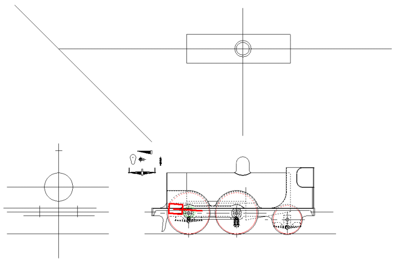
I drew in a test outline of scale cylinder dimensions today. In particular I was interested to see how things might work out, trying to get the piston rod, and the valve spindle either side of the leading axle. It's looking close, but workable.
I'm also beginning to think about the suspension, and particularly the springing for the locomotive. Notably the full size locomotive has leaf springs throughout, with the exception of the driving axle, which has coil springs. Thinking about making a good visual representation, I realised that I'd not be able to use the old dodge of cast lookalike leaf springs drilled out for a coil spring. This is because the springs are fitted below the axle boxes.
In practice, I could opt to use only coil springs, but these would have to be fitted under the axleboxes, mainly because the axles are so high in the frames, and there's already not much frame to incorporate the springs into the horns. With this in mind perhaps it's worth looking at following the full size locomotive and attempting to use working leaf springs. If they obviously cant work when I do the spring calculations, it's not that difficult to change the approach and opt for coil springs instead.
The first stage of this activity is to draw out some spring prototypes that look right, on the basis of available materials and scale. They may not be right, but it's a starting point for further examination, and preliminary calculation based on estimated axle loadings.
|