|
|
Sheet1 General Arrangement (Version 007)
Drawing Sheet
Notes
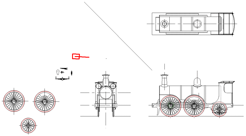
This time, we have the right number of spokes!
In drawing the wheels, I put some thought into the problem of obtaining the actual wheels, particularly in respect of the spokes. It's unlikely that if I make the engine, I'm going to be able to justify the expense of having wooden patterns made for the wheels then cast in iron. Sadly, though I have looked, I've been unable to find existing castings that match the requirement here, either in diameter, or by the number of spokes. That disregards the problem that balance weights, are unusually cast exactly between the spokes, rather than the more normal curved weights, or ones that are rivetted on afterwards.
My conclusion on this matter is that the wheels will be manufactured commercially. What I plan to do is have the wheels cut from steel blanks. The spokes will be cut by CNC waterjet, or pehaps laser. Then, for the driving wheels only the centre bosses, will be machined out with a ball end mill, on a CNC milling machine. The trailing and tender wheels, which are all the same and have no irregular boss, can either be CNC milled or turned at home conventionally.
The final result will be a wheel blank that I can then turn, much like a casting. The only significant difference is that the centre will already be drilled. Unlike the casting process, this will leave the spokes with square corners, but these can be dressed with a file. Most significantly the waterjet cutting scheme will allow the fine radii at the root of the spokes to be consistent and realistic.
|