|
|
Sheet1 General Arrangement (Version 001)
Drawing Sheet
Notes
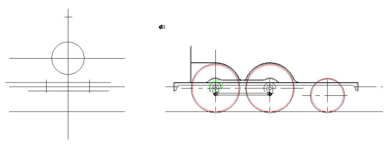
The first consideration was to set the thickness, of the platework for the cab, running boards, smokebox and splashers. This may seem a strange point to be considering such things, but the first realisation I had thinking about the chassis, is that the wheels are so big that there is very little room for the boiler. This was one of the big problems with early big wheeled locomotives. They wanted to keep the centre of gravity low so that the engines rode well. Obviously this was not a problem on Brunel's broad gauge, but for Stroudley on standard gauge, much more so. Anyhow, not only does the thickness of the platework for the splashers impact on the space between the wheels and the boiler, but also the position of the front of the smokebox.
Another important consideration is the clearance inside of the splashers from the wheels, given that the axles are vertically mobile under the influence of springs. This consideration leads into sizing of the wheel profiles, and particularly the flanges, which must not foul the splashers. At this stage, a nominal travel of 1/4" of the axles in the horns, is pencilled in. This assumes 1/8" either side of centre. In practice the boiler sizing constraint is so tight, that with the splasher thickness, this is the maximum allowable clearance inside the splashers. The travel in the horns will have to be constrained to just a shade less than this.
1/4" may not sound like much travel. It's important to remember that the suspension is only meant to lessen the impact of rail joints, points and such on the heavy chassis. In particular the position of the axle has a significant effect on the geometry of the valve gear. To keep the valve timing crisp, it's important that the axles aren't moving around too much.
Action commences
The first stage in the excercise was to get the wheel profile information from the GL5 website. Use of this information ensures that the wheel profile ought to fit through most ground level pointwork without fouling. Using this information it is then posssible to draw in the basic platework around the tops of the wheels, and set the position of the front of the smokebox.
Whilst working through this task I realised that it would be critical to know the loci for edges of the coupling rods, in order to ensure sufficient clearance for them inside the splashers. From reference pictures it was possible to determine satisfactory crankpin and coupling rod bearing sizes with an exterior shape of good likeness. The coupling rods were drawn in, and the pin centres determined for a good likeness.
|