|
|
Sheet1 General Arrangement (Version 002)
Drawing Sheet
Notes
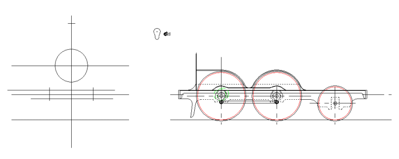
The focus for this effort is to deterine the frame outline. Unfortunately the pictures don't offer too much help. It is clear that the frames are very slight, since there is almost nothing visible of them above or below the running boards. In addition the splashers are so large it's difficult to say what is going on behind them. I know from reading around the subject that Stroudley was very keen to keep the engine as light as possible, and perhaps this was one of the mechanisms he used to achieve the aim.
The line drawings are fairly clear about the profile of the bottom of the frames, which is fortunate. These are easily scaled and applied to the drawing. Notably the guard irons are only drawn in for profile. The line drawings, and pictures confirm that the locomotive only has guard irons at the front. There are none on the rear of the tender which would be the modern practice. The locomotive was obviously not intended to run in reverse for any considerable distance. This statement is also consistent with knowledge about the way the tender is coupled to the locomotive. A special coupling was designed because of the large driving wheels with no leading wheels. That coupling would not have suited a situation where the locomotive was required to run tender first. The irons at the front would almost certainly be separate items bolted to the frames. None of th images or drawings I currently have indicate if they are bolted to the inside or outside of the frames. Clear direction on this will almost certainly be driven by a visit to the actual locomotive.
The top of the frames is more of a challenge. There are some clues, in that the frame clearly swoops up to the smokebox, in all of the pictures and drawings. This gives a clear indication of the frame height above the axle boxes. Oddly there is no visible indication of the top of the frame between the front and rear driving wheels. It is possible that the true line of the frame tops is not as hinted by the smokebox swoop. Nevertheless, the frames are so slight, that it is felt the line should follow the swoop, with a relief between the wheels for cosmetic purposes. Even with this height of the frames above the axle boxes, I still have some concern about the stiffness of the frames. Some sort of stretcher between the frames is, in this case, mandatory, but the detail must wait until the valve gear geometry is known.
The axle and axlebox sizes are set, but whilst doing this, I decide that the coupling rod ends are not right cosmetically. I make no changes, but resolve to find a good picture of a rod end from which to get the profile.
|