|
|
The system
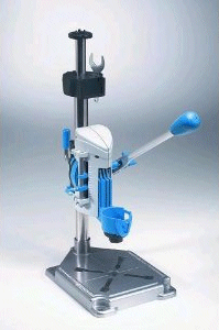 |
BOSCH ~ Dremel Workstation |
I don't sell this system, but I think it's the best thing I've seen in a very long time. Perhaps I should sell it!! I'm not going to mention the supplier of the product involved, because I have no affiliation with him. Nevertheless if you've read this far, and you're interested in making any kind of instruments (including circuit boards) I would recommend you scour the web for the site that sells the products.
I'm going to talk generically about the materials that make this system work so well. I'm interested enough in this system that I've figured out how to make the materials at home. You can too, and so I'll describe how to make them. That said, I've made them, and I get better results with the materials I've purchased. I suspect you will too.
The basic technique uses a laser printer, and transfers the toner from a paper sheet, in theory to almost any surface. Start from that perspective. Think about almost any artwork, colour if you have a colour laser printer, and the ability to produce those printed images on anything you like. That's more or less what this comes down to. The applications are endless. Promotional items, t-shirts, drinking glasses. Importantly to me, instrument panel artworks, and circuit boards.
There is a wealth of stuff on the web suggesting that one can use glossy inkjet photo paper for this purpose. I would recommend against that, simply because it's only so good. It does work, but it's awkward, and the image quality is not what I might describe as perfect. Perfection is possible.
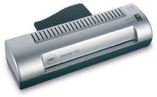 |
GBC H65 Laminator |
I'm going to assume you've already got the schematic entry and PCB routing aspects figured out. If not, make sure you do, because it's free, and it's worth it, even if you can't justify having a commercial PCB made.
The major capital investment for this system is limited. You're going to need a laser printer, an A4 size pouch laminator and some sort of drill that can achieve more than 1000 rpm. I didn't have a laser printer so I got one from e-bay. I think it cost me £25, and it now does all my letters as well. The pouch laminator was the most expensive part, I think I got mine from Amazon, and it cost me £55. I already had a drill press capable of the task, so that part was free, but I feel sure that one could obtain a Dremel style drill with a stand for less than £100.
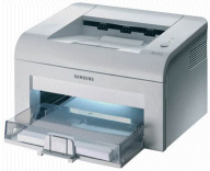 |
Samsung Laser Printer |
I'll walk through the basic scheme step by step with pictures on the next pages. We're going to;
- Take a black and white artwork, printed on a "special" paper (I'll call it gummed paper), and transfer it to a copper clad board using the laminator.
- Improve the density of the image on the copper clad board, again using the laminator, along with a "special" film (I'll call that typists carbon replicator film), which will melt plastic powder into the artwork. This will make completely certain that no acid etch can get through the artwork.
- Etch the board, using less than an egg cup full of acid.
- Tin plate the developed tracks.
- Drill the holes for the components.
- Populate the components onto the board.
Overall, I'd say that the complete process takes just less than a day, to go from a rough drawing of a moderate circuit on a piece of paper, to a completely finished and professional looking prototype. You could probably do it faster, but it's certainly comparable with stripboard.
|


