 |
 |
 |
 |
 |
 |
|
Making the PCB (Part 1)I'm going to demonstrate the manufacture of a single sided PCB here. Double sided is no problem either. This board exclusively uses through hole components. They could be surface mount, but I think for little experiments and side projects through hole makes the most sense. There's no reason why you couldn't mix technologies either. One of the most powerful capabilities of PCB's is that one can accommodate "non standard devices". By that, I mean components that have pins, but the pitch of the pins is not 0.1". For home made single sided PCB's, it's important to remember that we will produce vias on the PCB artwork, but that we will not be using through hole plating. This is an important reason why single sided boards are so attractive. If you do chose to do double sided boards you will need to solder a through wire for each via, on both sides. The same is true for component pins when using through hole devices. This limitation leads to some interesting problems in the PCB layout software. The component copper layer effectively becomes the "wire link layer". Normally on a multi layer board the through hole plating allows one to minimize explicit vias by using through hole components. We'll draw the single sided board as a two layer board, but we must remember to ensure that vias are only connected to a single wire link, and that the wire link only routes through the spaces between components. If this rule isn't followed the board can't be made, unless the wire links are installed on the reverse of the board. Typically it's better if the links are straight but this is usually too onerous. Allowing links to have one 45 degree bend makes routing pretty straightforward. I have found KiCad schematic / PCB software to be free, and have all the capability I need for these simple designs. I manually route these simple boards using a fairly crude routing scheme. Typically I set a 0.030" track with a minimum gap of 0.008". I typically design component footprints around a 0.076" pad, which allows an 0.008" track to pass through an array of pins spaced equally at 0.1" pitch. Usually I avoid reducing the track width, but it's possible and works. Getting down to it - Cutting out the blankBy whatever means print your fully routed and checked artwork onto a sheet of paper, at accurate full size. Use a knife to cut the board outline out of the sheet, so that you have a template to cut a blank board from. Get a sheet of the 0.032" (0.8mm) 1/2 oz copper clad board, and place the paper template onto it. Pick a suitable place to cut it from. If you want you can use tape to stick the paper template to the copper clad board, but I usually hold it in place, and use the knife to just score the copper lightly at the corners. Once you have your alignment marks, you can use a straight edge to join the initial marks. Using the knife score between the marks a couple of times, so the overall outline is clearly defined in the copper. At this stage you're not aiming to get through the copper with the knife, merely get a nice accurate overall outline. If the board has cut-outs that make it other than square leave them, until you have the complete blank, loose and separate. Once you have the overall outline, nice and accurate using the straight edge, you can lose the straight edge, and use the knife to score through the copper, and into the fibreglass. It may sound odd, but I have found this to be the best way, because the straight edge can slip, and the line becomes wobbly or ill defined. If you use the right amount of pressure the knife will follow the score mark accurately, without the straight edge. Repeat scoring, perhaps ten times, and turn the sheet of copper clad over. You should see the scoring begin to appear as a light coloured mark on the reverse, non-copper side. You can see the light marks, not because you're nearly through, but simply because the fibreglass is almost transparent. Using these light marks, and the straight edge, you can begin to score the copper clad from the other side. At first use the straight edge, then go freehand. You'll begin to get a feel for it, but at some point the scoring will weaken the board to the point where it will begin to creak if you bend it, even lightly. Keep scoring from both sides until this happens. Once it does you should be able to literally "peel" the board blank out of the copper clad sheet. 
The diagram above shows the tools and materials to get the basic board blank. You can see that the template has a cut-out which I've dealt with in the same way, in the next picture. You'll see I've moved out to the workshop, where I have a vice. I typically use the vice with soft jaws. I also hold the board blank in the vice with a clean rag placed between the soft jaws and the blank. This ensures that the copper can't be marked by the jaws. Once secure, I just use a small file to square up the cut edges of the blank. The same file is used to remove any copper burrs that have developed along the board edges. Cleaning the blankOnce you have the basic board cut out, and nice clean edges, you can focus on cleaning up the actual face of the copper that we'll apply the toner to. It has to be spotlessly clean. To start with use a new ScotchBrite pad (green pot scourer) to abrade the surface and remove the copper oxides. You can use cheap scouring pads, but I'd recommend getting ScotchBrite. It's not that much more expensive, it's still available at the supermarket, and it's the de-facto standard in industry. We're not cleaning pots here. We're after "chemical clean". ScotchBrite is ever so slightly more abrasive than the generic products, and has greater "scratching power". 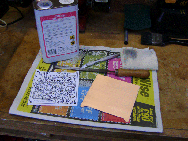
Using the scourer, work in straight lines, until the whole of the board has a nice sheen with straight lines. Pay particular attention to the areas near the board edge, which are more difficult to get clean. Once satisfied, turn the blank through right angles, and go again, until you can see the two different patterns in the metal. Then turn through 45 degrees, repeat, and then another right angle. When you've finished you should have a shiny surface, and you should be able to see all four patterns in the light. At this stage it's really important not to get finger prints onto the copper surface. Try as hard as you can to avoid them. Get a brand new, clean rag. I usually cut off a new length of cotton cleaning hose, from the local motor factor, but you could use blue paper Kimwipes too. Kimwipes would probably be better, but the cotton is pretty nearly as good. Use the rag, to apply fresh Isopropyl Alcohol to the surface. I just use IPA from Servisol, it comes in nice big cans. Wipe along each of the four grains you introduced with the ScotchBrite. Initially the rag will come up black, which is the metal oxides and plastic from the scourer lifting from the surface. (And it looked so clean!!). As the muck comes off the surface keep moving on to a clean section of the rag, and apply more alcohol. If necessary use another new clean rag. Once the rag comes up clean, you're done, and the board blank is ready to receive toner. At this stage it's really best to protect the clean surface from muck, grease and so forth. Probably the best way to do this is to fold a clean sheet of printer paper in half, and place the board in the crease. Handle the board only through the paper. So, we've got the basic shape of the board sorted out. Using the ScotchBrite, we've keyed the surface, to give something for the toner to stick to, and we've brought the surface of the copper to a state of cleanliness, that is probably as good as it would be possible to achieve without spending considerable money. If you have Ultrasonics, Sulphuric etch, or a Trichloroethylene bath, feel free to use them. What we've done here, if followed carefully will almost always yield perfect results. On the next page, we'll see how to apply the toner. |


Copyright © Solid Fluid 2007-2025 |
Last modified: SolFlu Sat, 03 Jul 2010 00:18:36 GMT |