 |
 |
 |
 |
 |
 |
|
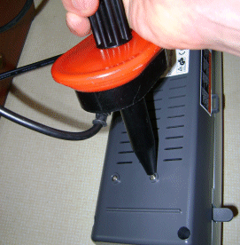
PreparationI've already briefly mentioned the general tools and materials that you'll need to get started with all of this. Getting the tools and materials right, is quite important. I'll assume that you already have the main things, but there are a few issues to contend with right off bat. The LaminatorThe process of using the laminator to transfer toner from the gummed paper to the copper clad board is quite critical. From an operator perspective, there is very little skill required to get it perfect, but if the basic conditions aren't right, it just won't work properly. Probably the most critical aspect of the process is re-melting the toner from the gummed paper onto the copper clad board. Unless your laminator has a rotary temperature control, and a temperature reading, it probably won't be hot enough to do the job. I've recommended the GBC H65 Laminator because there is information out there, on how to modify it, such that the process will work properly. I'll explain this, but if you chose a different machine then the explanation won't fit with your laminator. In this circumstance you will need to know that the temperature at which toner will re-melt without becoming runny, but liquid enough to stick to your board when it cools, is 150 degrees centigrade. Another problem with the process of getting toner onto objects, is that the laminator will only accept sheet of a given maximum thickness. I'll come to this in more detail later, but if like me it's useful for you to apply graphics to sheet metal like brass and aluminium then the laminator will probably not be enough. The sheet metal will probably be too thick. In this case you can use an ordinary clothes iron to provide the heat. The Iron method
The picture here shows my most successful attempt using home made gummed paper to do the transfer. I did this before buying the laminator and the "proper" materials as a test. For the actual transfer I used an ordinary clothes iron to do the transfer. In the interests of precision I had to calibrate the iron, and I simply used the temperature probe with my multi meter, to set the dial on the iron. After a couple of minutes I was able to observe the temperature fluctuating around 150 degrees as the iron heated and cooled in free air. In this case I printed to gummed paper and put the paper at the bottom, with the brass between the iron and the paper. This avoids the problem that steam irons have grooves in the soleplate, and it affects where the heat is applied. If you have a steam iron, obviously don't use the steam settings. Layering the paper and the brass in this way uses the metal to spread the heat about. Some hand pressure is needed, but not lots. Transfer should be achieved in less than a minute. As with all of these processes, the adhesion of the toner to the metal surface is uncanny. If it sticks, it sticks really well. You could scratch it off with a metal stylus or chisel, but your fingernail wouldn't remove it at all easily. It's notable that Isopropyl Alcohol won't easily remove the toner, but Acetone will. This sets out the cleaning regime. Before applying toner, always clean with IPA and avoid fingerprints. If it doesn't work, you can easily wipe the toner away with Acetone, and clear up with IPA to simply try again. The copper clad boardI've mentioned that the thickness of the material put through the laminator is important. The poor old laminator was intended for paper products. It would be possible to make the mechanism adjustable, but it has only really been designed to deal with 0.025" (0.64mm) thick materials. It is capable of working on 0.032" (0.8mm) materials, but that really is the limit. It's probably pretty fortunate that you can get commercial 0.8mm laminated FR4 copper clad board with a 1/2oz copper layer, because it just about squeezes through. Don't make the mistake of trying thicker board. It won't go through the laminator, and then you have to use the iron. The laminator is such a repeatable way of applying the heat, it's worth sticking to. With a clothes iron you can go wrong. With the laminator it's a no-brainer. I originally thought that the 0.8mm and 1/2oz board was a limitation. In many ways, it really is, but it's no way as structurally weak as you might think. Having made quite a few four and eight layer boards, this thin board had previously seemed wrong. In the context of a low volume prototype, it's really not. It's actually an advantage.
Modifications to the laminatorSo, perhaps you've done a bit of thinking, perhaps even some tests as I did. If you decide to use the laminator, you're going to have to modify it, such that it has a setting capable of achieving the 150 degrees centigrade critical temperature. You can try to use the laminator without modification, but it unfortunately won't cut it as it is. The laminator is a 240VAC device, make sure it's unplugged before you start, and be under no illusions; Mains voltages can kill - if you're unsure, get help from a qualified professional. Even if you do proceed, you do so at your own risk. Modifying the laminator will invalidate the warranty, and may cause injury or death. We cannot be responsible for any damage caused. Put the laminator on it's back. It should look like the following picture; 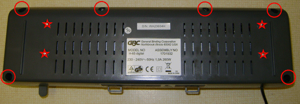
The screws with a circle around them, need to be undone. The ones with stars, should be left alone. They hold the mechanism into the bottom of the unit. We don't need to remove the mechanism, just the cover. The circled screws along the front edge and in the middle are slightly shorter. Remember which screws go where when you come to reassemble the unit. Once the cover is loose, turn the unit over and lift the top off. Carefully hinge the cover up and to the back of the unit. 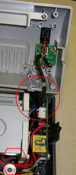
At the right hand end of the unit, the temperature control board, is held in by the connectors and a gland inside the circle. Also inside the hexagon a screw holds the wires away from the heater. The board it's self has only a guide slot to hold it in place. Carefully make a note of were all the connectors go, and remove them. Also remove the screw, and be sure when re-assembling to ensure that the wires are retained away from the heater, to ensure they cannot cause a fire. Once you get the board out it should look like the picture below. 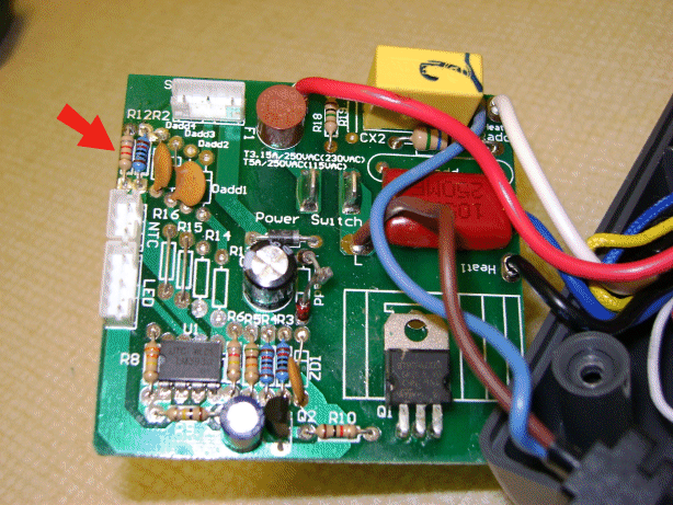
At the very least you'll need to replace the resistor arrowed. The unit has a temperature selector switch, allowing selection of two heater ranges. The resistor with the arrow is the high temperature range resistor. The one next to it is the low temperature range resistor. When doing ordinary paper laminations I generally use thicker lamination pouches, so I moved the old high temperature setting to the low temperature setting. Then I was able to put the new super high temperature onto the old high temperature setting. If you want to increase the low temperature setting, that's up to you, but in any case the arrowed resistor needs to be changed to an 8K2 1/4 Watt or better resistor, as I have already done in the picture. This sets the the upper temperature to 150 degrees. 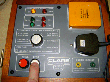
Once you're done, put everything back together. If you can, do a safety test on the unit, as I did above with my PAT tester. The HT probe of the PAT tester is touching the screws that protrude and hold the heater assembly into the case. Generally the unit is double insulated, but the case is tight inside, and this prevents any worry that a mains wire became squashed against the internal metalwork. When you're done the laminator is ready to make PCB's. A final note about the materialsI mentioned about the "Gummed Paper" for transferring toner to metal in the laminator, and also "Typist's Carbon replication film". The latter I've not experimented with, but I'm fairly sure about. The gummed paper is simply that. Stateside, there is someone selling gummed paper for this purpose, and it is very high quality. You can make your own, but the amount of research that chap has done, must be quite great. It's worth buying because he's got it just right. Nevertheless, it's moderately expensive and for fun, or practice, you can make your own and it will work to a reasonable degree. As far as I can tell, the Gummed paper is just that. You can buy such paper for making labels. You print on the non gummed side, and the label can be stuck to a parcel. We're going to print on the gummed side, as we'll see later. There's nothing magical about the gum. It is simply corn flour and water mixed - Dextrin. The resulting glue can be improved by baking the flour beforehand for a couple of hours until it turns golden yellow. To mix the flour and water you'll probably need to warm the water until you get a thick goop. It's the same deal as paper mache. Jellies too for that matter! The big deal, is getting the gum onto the paper evenly. I did various experiments with an airbrush, but the best results came with a small sponge roller. The other more serious problem is preventing the paper from curling. Somehow you have to get it through the printer. I think that's mainly down to the paper type, and the speed of drying. I had mixed success, but I can assure you, when you get a nice evenly gummed flat paper sheet, homemade works a treat too. The density film seems to be typist's carbon film. I'm pretty sure it's not the old fashioned blue sticky stuff. It's the more modern plastic film type. It's very thin, and it has a fine powdery surface on one side. When one types through it, the powder sticks to a sheet of paper. As I say, I've not tried it, but if you can get some cheap and in bulk, it could save you some pennies. In truth the American source of this material is such good value, it's not worth trying to go for an alternative source. I guess I'm just preparing myself for the possibility that that chap may not be selling his stuff forever. Now I've been through the "one time" preparation we can proceed. Some of the stuff above may not yet make sense, but I think once you've seen how the board comes together, you might want to "dip in" to this page as a reminder. |


Copyright © Solid Fluid 2007-2025 |
Last modified: SolFlu Sat, 03 Jul 2010 00:18:42 GMT |